A ground-testing platform for rocket flight-control hardware.
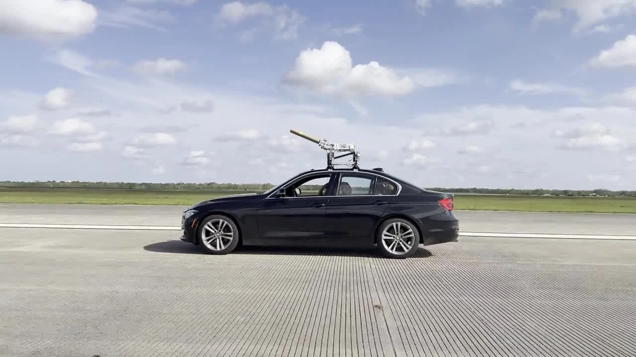
Over two semesters, our three-person team built a portable rig that holds a rocket section on a car roof and changes its orientation as the car moves. This lets Rice Eclipse test hardware under airflow before using it in a launch.
TVC structure design · CAD & FEA · CNC part fabrication · Actuator movement code · Testing
PROJECT OVERVIEW
How the rig works
Pitch: nose up or down. Yaw: side to side. Roll: rotation along the rocket.
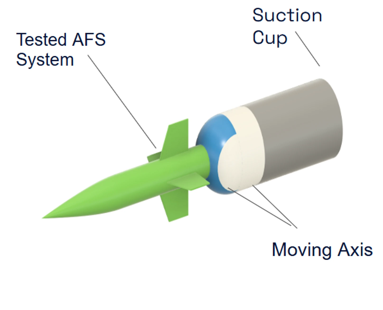
Active flight stabilization (AFS) uses movable fins to correct a rocket’s orientation. Our project is the test rig that supports that hardware. It creates controlled changes in the rocket section’s orientation so the client can study how its system responds.
01
Hold the rocket in the airflow
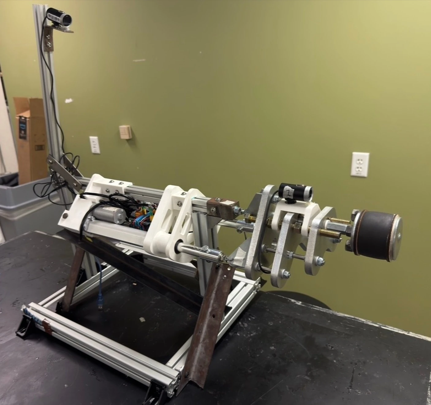
The frame attaches to roof racks. An expanding pipe plug grips the inside of the rocket tube, leaving the outside accessible for testing.
02
Set its orientation
Two linear actuators extend and retract around a fixed central pivot to control pitch and yaw. The spring mount adds a bearing-supported roll axis, which can rotate freely or be locked with bolts.
03
Control and record a test
The operator enters angles in the team’s interface. Our code converts them to actuator lengths; an Arduino and motor drivers move the rig while mounted cameras record the test.
Spring 2026 rig, shown without the rocket section. The pipe plug at the front fits inside the rocket tube.
FALL 2025
First working rig
Built and programmed the pitch/yaw mechanism, added camera mounts, and tested it on a vehicle at up to 40 mph.
SPRING 2026
Improved mount and structure
Added free roll, used FEA and physical prototypes to revise the hardware, and tested the rig at Ellington Airfield. The poster records a maximum vehicle speed of 105 mph.
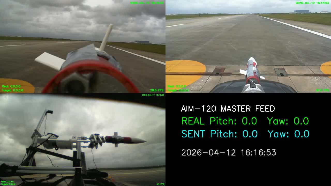
Watch the rig operating at the airfield +▶ Play the airfield testVehicle-mounted test at Ellington Airfield · March 24, 2026 · Silent excerpt
01 / DESIGN PROCESS
Clarify the assignment
Rice Eclipse needed a way to test its stabilization hardware more frequently, without launching a rocket for every trial.
We worked with the client to define a portable platform that could support a rocket section, move it through different angles, and carry cameras or other test equipment. It needed to attach securely to a car and remain adaptable to future wind-tunnel testing.
The fall semester focused on building a working pitch/yaw rig. In spring, the assignment expanded to include free roll, a more secure rocket mount, less structural flex, and higher-speed testing. We kept the same overall approach while revisiting the parts that limited it.
OUR PROJECT SCOPE
We designed and tested the rig’s motion and supporting hardware. Rice Eclipse was developing the active-fin system itself; testing the completed AFS system with the rig remained a separate step.
02 / DESIGN PROCESS
Understand the problem
We first needed to understand what the AFS system would do and what might interfere with its testing. The mount had to hold the rocket firmly without blocking the fins, allow movement under wind loading, and leave space for cameras.
Our background research included sting and strut mounts used in wind tunnels. Those examples helped us think about support location and airflow interference, but our rig also needed controllable motion and a portable base.
Rice Eclipse’s AFS concept—the rocket hardware our rig is intended to test.
Breaking the problem into three parts
Rocket mount
Secure the tube, accommodate its fit, and avoid interference with the fins. Spring work also needed a way to support free roll.
Platform mount
Attach the rig to the test vehicle, support wind loads, and provide mounting points for recording equipment.
Rotation mechanism
Use motors, joints, and control code to move the rocket through the requested pitch and yaw angles.
03 / DESIGN PROCESS
Design criteria
We used the client’s needs to set measurable targets. Motion and structural integrity had the highest priority: the rig would not be useful if it could not reach the test angles or hold the rocket securely. Portability and accessory mounting also shaped our choices.
Key requirements across the two semesters
Requirement
Target
Why it mattered
Range of motion
Pitch and yaw: ±20° Free or locked roll in spring
Let the client test different orientations and observe roll response.
Structural integrity
40 mph initial target 85 mph final test target
Support the rocket and maintain motion under wind loading.
Portability
Carried by one person
Make setup and transport practical for the student team.
Accessory mounting
At least two devices initially; additional cameras and accessories in spring
Record the hardware’s movement during a test.
Secure attachment
No parts detach during testing
Keep the rocket, rig, and vehicle connections secure.
Size
Vehicle + rig within 14 ft total height; rig within a 6 ft cube for future tunnel use
Fit the planned test environments.
These are design targets from our documentation, not a claim that every requirement was fully validated. The final testing section shows what we measured and what still needed work.
04 / DESIGN PROCESS
Brainstorming
88 ideas →6 concepts
We held two brainstorming sessions across the three design blocks, producing 88 ideas. We screened out impractical ideas and combined partial solutions into six complete concepts for comparison.
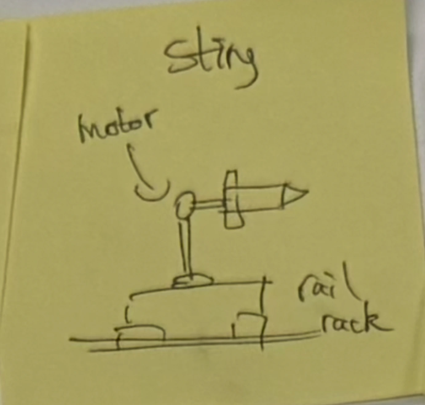
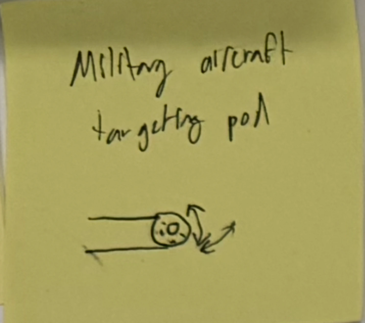
The options explored different ways to hold the rocket and attach the base: a four-spoke frame, rear-mounted stings, body-supporting struts, and a gimbal inspired by an aircraft targeting pod. We paired these with roof rails or suction cups.
Four-spoke frameSupport the rocket around its body and use the spokes to change its angle.Sting + roof railsSupport from the rear to keep the area around the fins more open.Targeting-pod gimbalUse a rotating mount to point the rocket in different directions.
Brainstorming again in spring
The first prototype gave us more specific questions. How could we grip different rocket tubes and still allow roll? How could we reduce bending in the center support and printed joints? We explored expanding mandrels, fit-up clamps, and pipe plugs for the mount, along with machined connections and several frame-reinforcement ideas.
05 / DESIGN PROCESS
Evaluating concepts
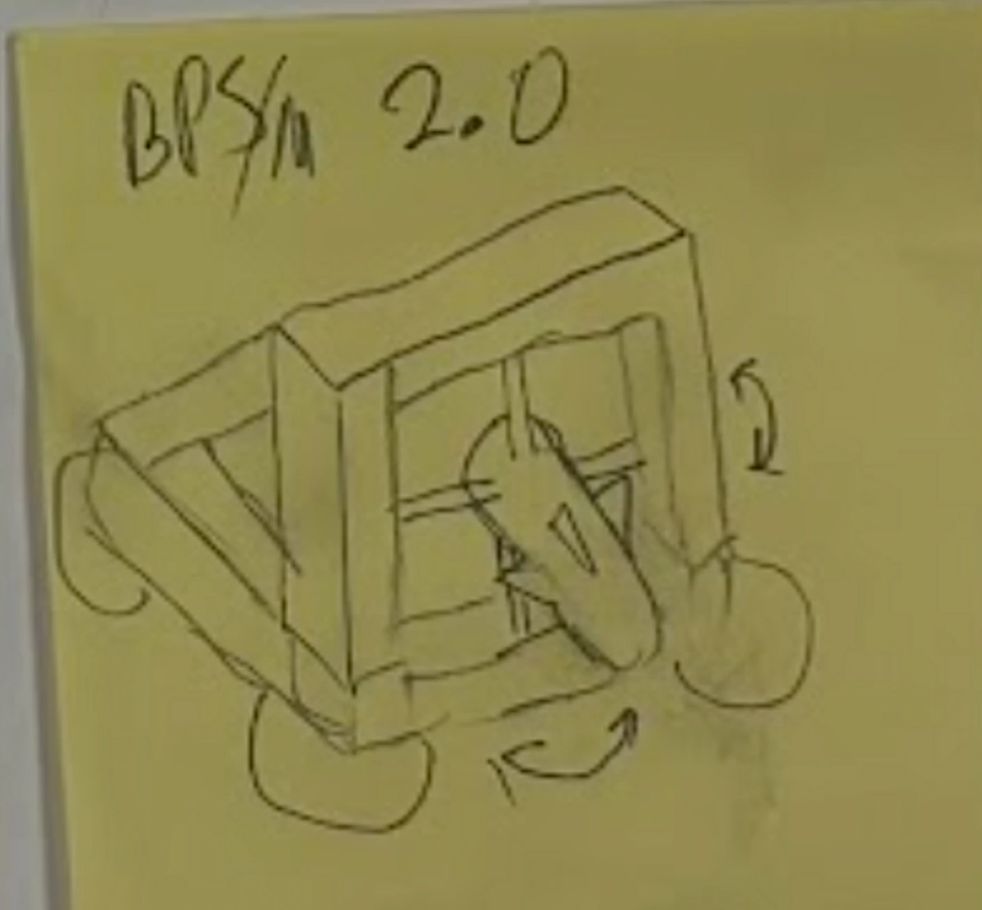
Initial gimbal concept, selected during scoring and later reconsidered.
Why we changed the first concept
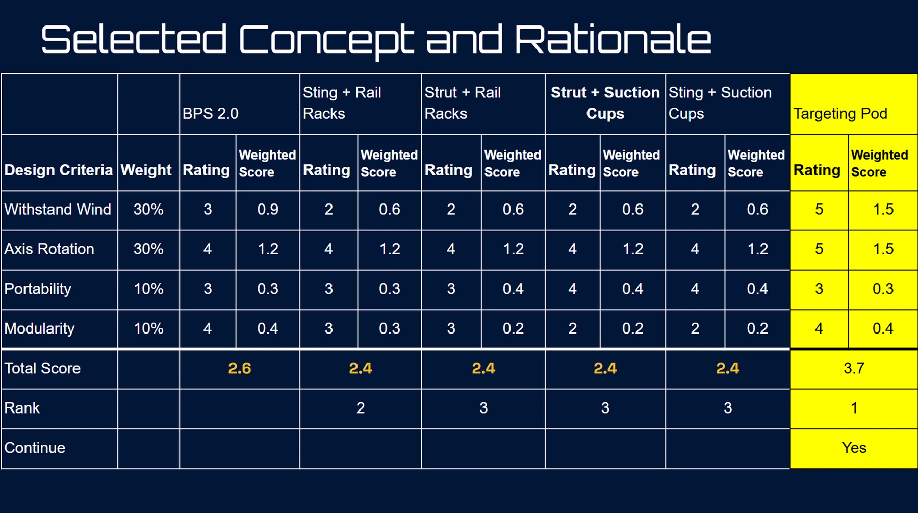
Our weighted scoring chart ranked the targeting-pod concept highest, particularly for expected wind resistance and range of motion.
During early prototyping, however, the torque needed to hold the rocket against gravity and wind became a problem. Larger actuators would have made the design less portable and more expensive.
THE REVISED APPROACH
After discussing this with our faculty mentor, we adapted a thrust vector control (TVC) mechanism. Instead of pointing a rocket nozzle, two linear actuators point the rocket test section around a fixed pivot. Their self-locking mechanisms also help hold position under load. I worked on the TVC structure design and the code that converts angles into actuator movement.
View our original concept scoring sheet +Original team scoring sheet. We revisited this selection when prototyping exposed the torque problem.
Choosing a mount that could also roll
In spring, we compared three ways to grip the inside of the rocket tube. We needed adjustment for tube-size variation, a supported rotating shaft, and parts we could make or buy within our budget.
Spring rocket-mount options
Option
What we found
Expanding mandrel
A useful precision-gripping approach, but the options we found had too little expansion range for the client’s tube-diameter variation.
Fit-up clamp
Accommodated different pipe sizes, but cost more and needed an additional mechanism to allow continuous rotation.
Pipe plug · selected
Affordable, adjustable, and simple to install. It still needed our own shaft, bearings, and centering features to work as a rotating mount.
06 / DESIGN PROCESS
Prototypes & iterations
FALL 2025 → SPRING 2026 CAD · FEA · Fabrication · Controls
We used CAD, finite element analysis (FEA), printed parts, and physical testing together. Each revision addressed a problem we found in the previous version. My main work included CAD and FEA, machining CNC parts, the TVC structure, actuator movement logic, and testing.
A
Fall: build the first working rig
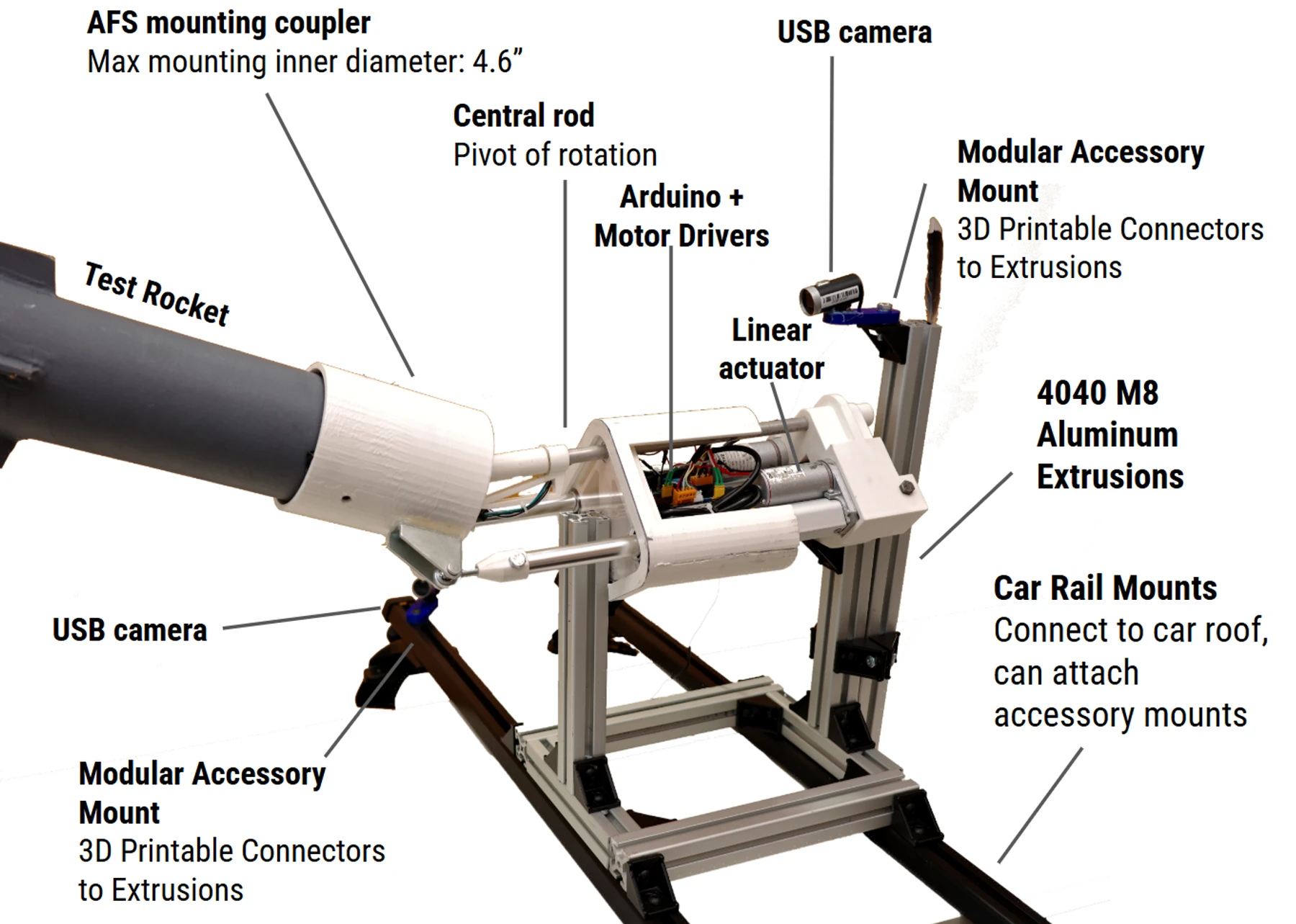
We assembled an aluminum-extrusion frame on roof racks, an external rocket coupler, a central pivot, and two linear actuators. Printed parts let us check the layout and connect the actuators and joints before committing to more machined hardware.
I worked on the movement logic: for a requested pitch and yaw, the code calculates the required actuator extensions using the geometry of the mechanism. The Arduino and motor drivers execute the motion. The team’s interface brings together angle inputs, camera views, and recording.
The fall prototype, with the main components labeled. Click any project image to enlarge it.
The first vehicle tests showed that the mechanism worked, but printed connections could flex, the external coupler needed a more secure fit, and roll was not yet available. Those findings guided our spring redesign.
B
Spring: redesign the rocket mount
We initially tried improving the external coupler, but its diameter affected actuator spacing and made it difficult to adapt to different rocket tubes. Large bearings were also hard to fit, and the complex coupler would be difficult to machine as one piece. We moved to an internal pipe plug carried on a rotating shaft.
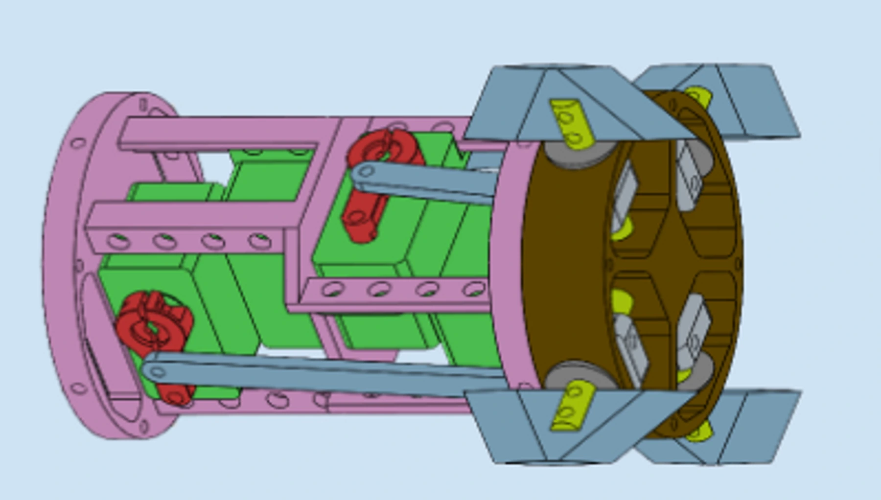
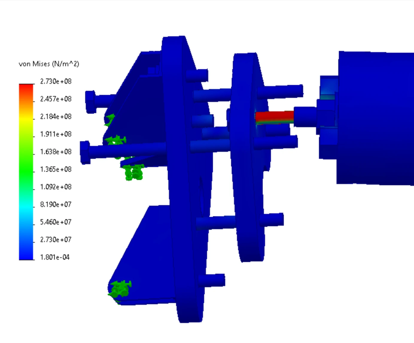
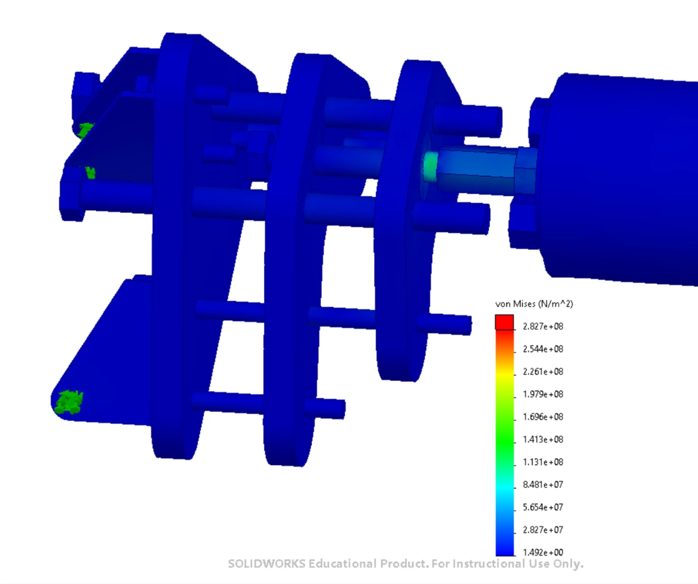
The first version supported that shaft with one bearing. In a simulation with a 40 N load at the rocket tip, it predicted failure at the shaft and high stress in the supporting bolts. We added a third plate, a second bearing, and thrust bearings to spread the load and support the shaft.
BEFORE One bearing; concentrated shaft stress.
AFTER Third plate and a second bearing.
With the same 40 N load, the revised free and locked configurations had modeled factors of safety of 2.5 and 3.5. This gave us a basis for building the next prototype, while still needing physical tests.
The simulation used the documented load and constraints; these values do not describe every possible operating condition.
C
Check the fit, then machine the parts
Before machining the three plates, we printed a version and assembled it with the actual bearings and bolts. This was especially useful while I was learning the CNC process: the assembly revealed problems that were not obvious in CAD.
Bearings could push out. We replaced through-holes with counterbored seats that provide an axial stop.
Locking bolts blocked joint pins. We shortened them from 7 to 6.5 inches to provide clearance.
The rocket wobbled when rotated. Laser-cut centering washers helped align the pipe plug with the tube.
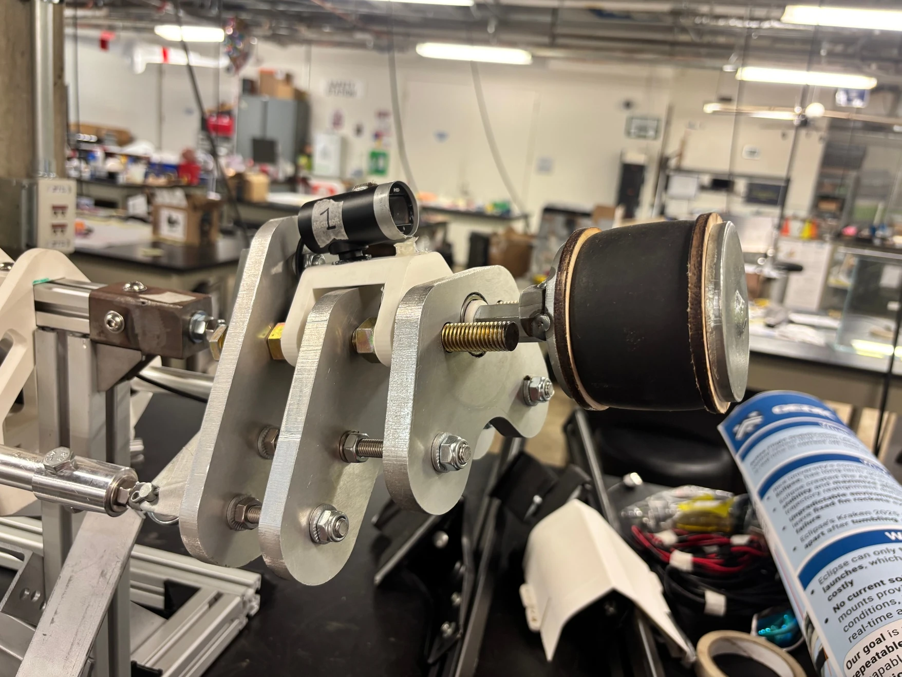
We then machined the plates and assembled the mount, including a through-hole for wiring. Two bolts allow the roll axis to be locked for static tests.
The machined mount after the printed fit-check prototype.
D
Reinforce the frame
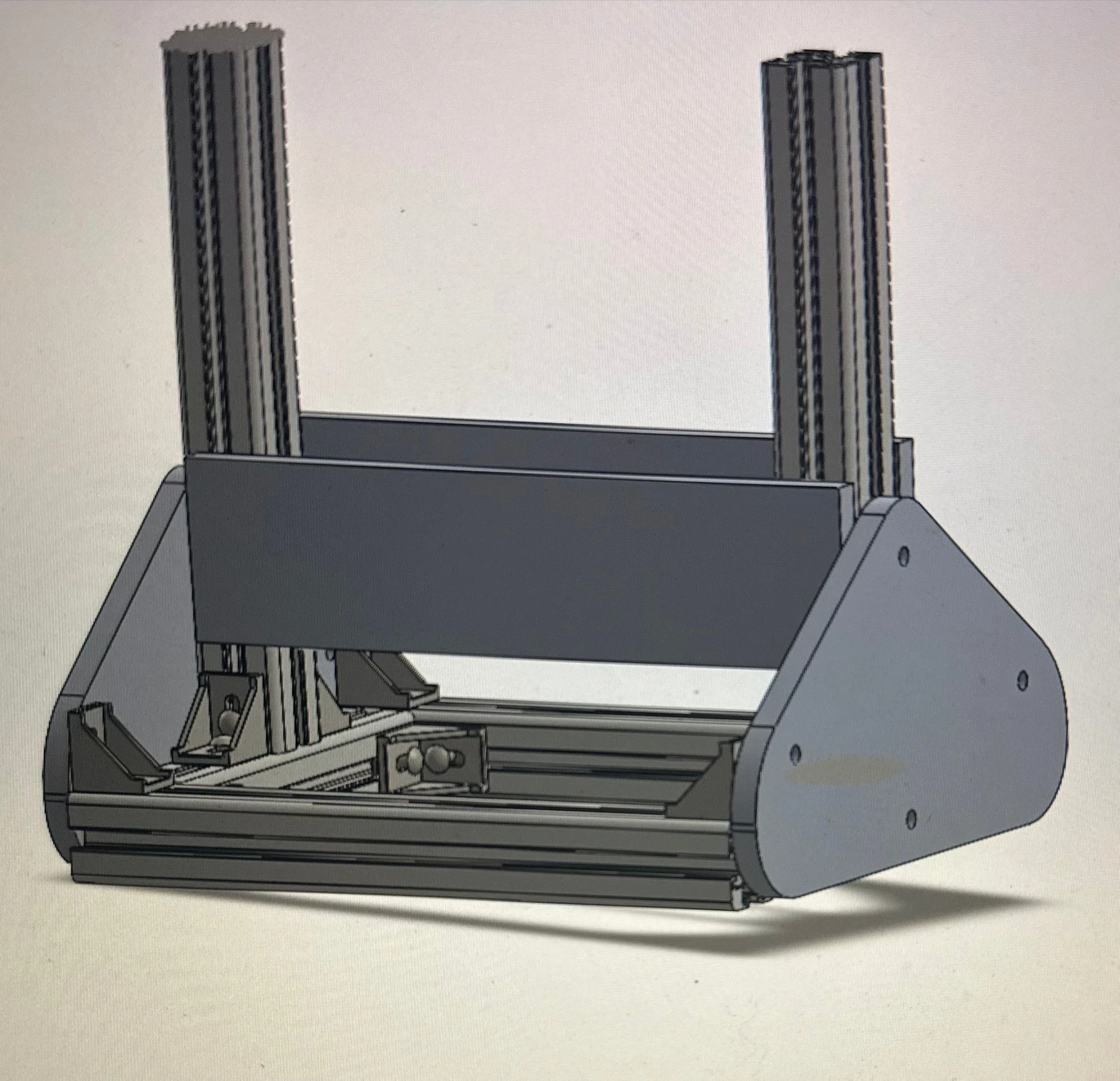
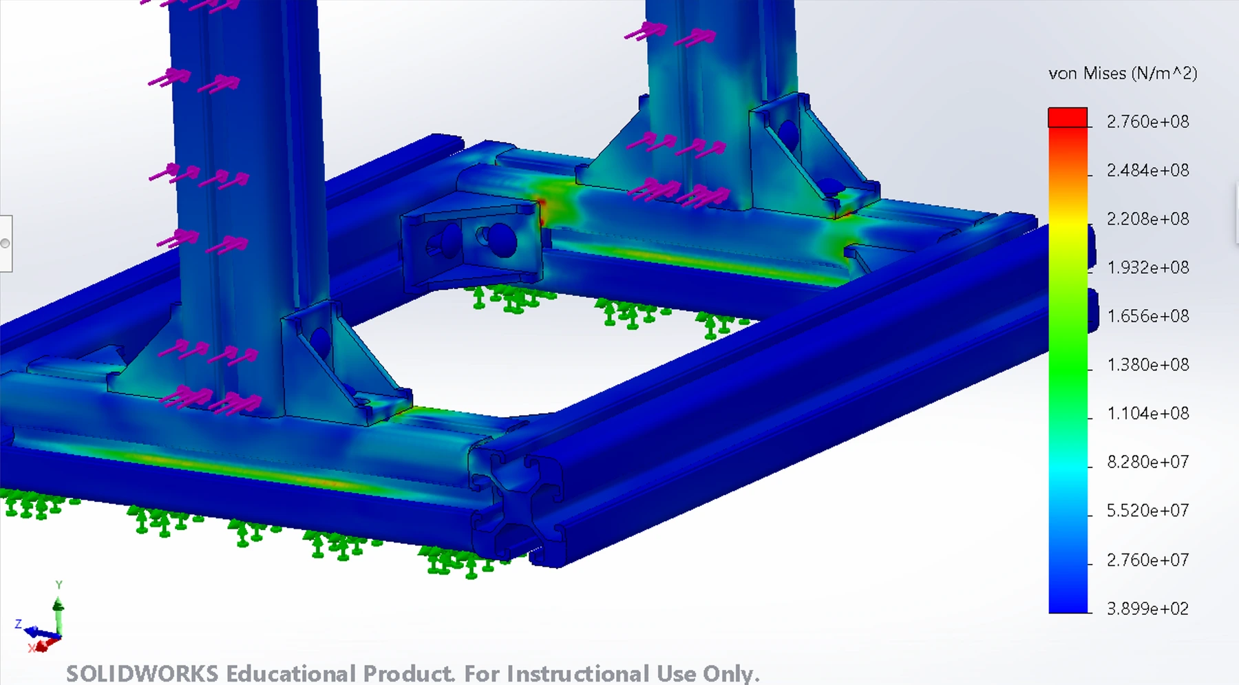
Frame FEA at 200, 300, and 1,000 N showed stress around the connections to the vertical extrusions. We first modeled large reinforcing plates, but their wind-facing area could increase loading, and they mainly resisted bending in one direction.
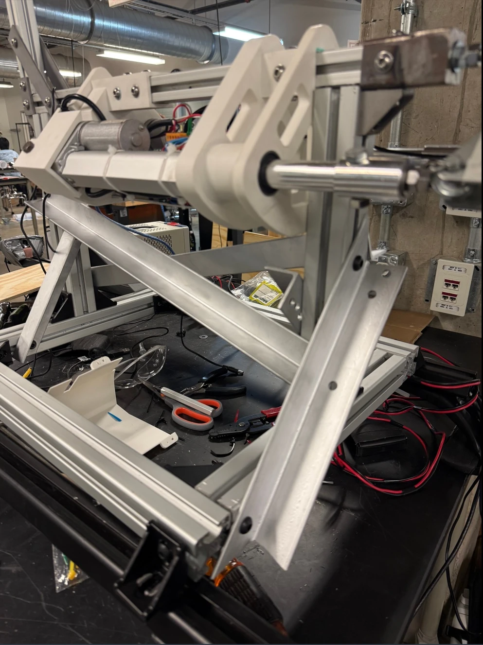
CONSIDERED Large reinforcing plates.BUILT Smaller, triangulated aluminum angles.
We used aluminum angles to brace the frame in multiple directions with less exposed area. The braces fit the existing extrusions and hardware, though they added weight.
See the frame FEA load case +
One of the frame load cases. The forces were estimates used for comparison, not measured aerodynamic loads.
E
Reduce play in the motion mechanism
The thin center tube could bend under load, so we replaced it with a 2525 aluminum extrusion and redesigned the surrounding plates. Linear bearings added support around the actuator rods, where clearance in the actuator housings had allowed unwanted movement.
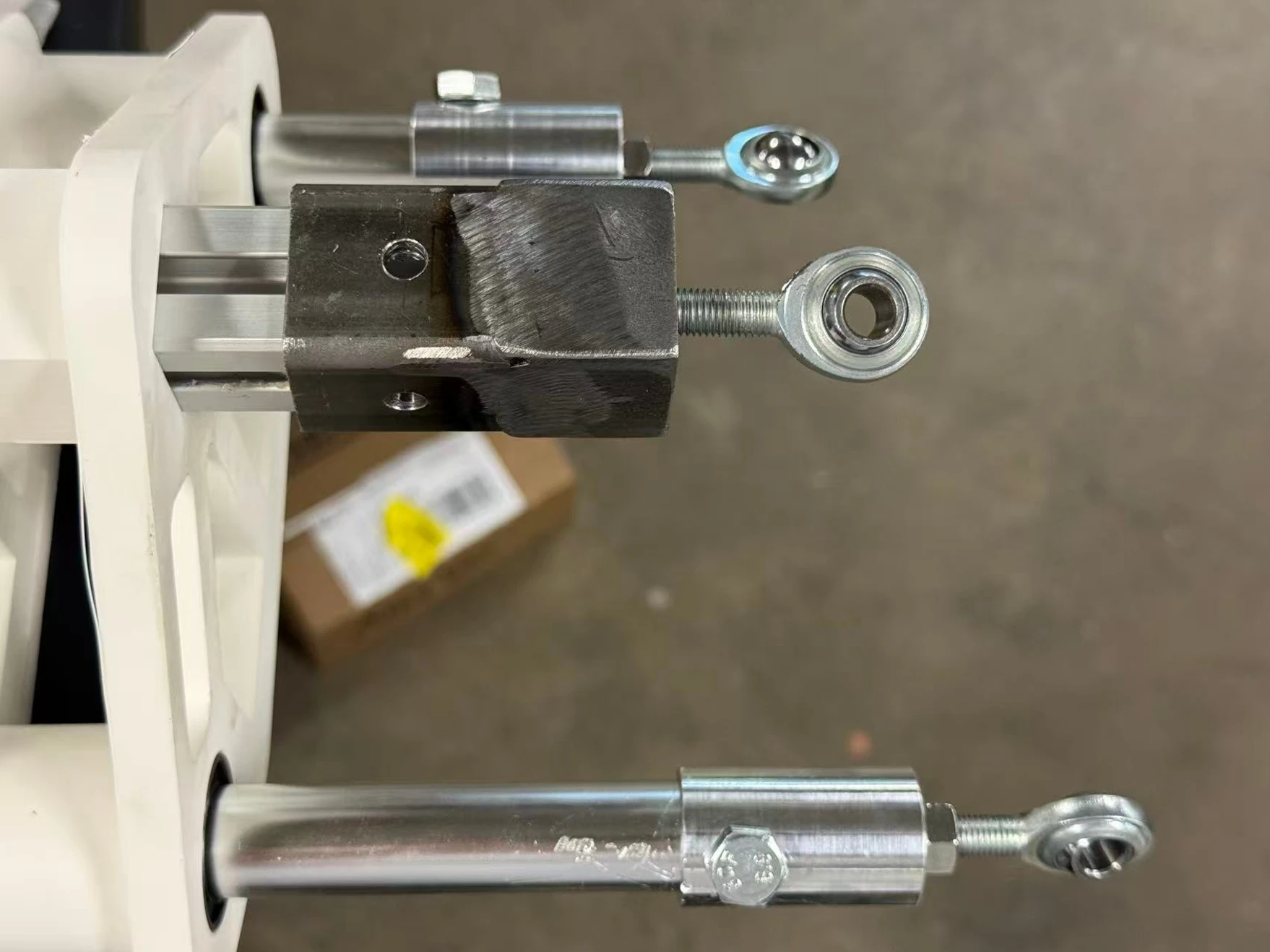
We also replaced flexible printed actuator ends with machined parts. For the center connector, the team used welded steel pieces to connect the extrusion to the spherical joint. These changes made the mechanism stiffer, but testing still showed interference at some extreme positions.
Revised actuator ends and center connection.
07 / DESIGN PROCESS
Test the solution
BENCH & VEHICLE TESTS Fall 2025 and spring 2026
Fall tests: motion, structure, and portability
We tested the first rig in two 10-minute vehicle sessions at speeds up to 40 mph. It moved through ±20° pitch and yaw with no visible frame deformation or loosening during those trials, and the camera mounts stayed secure.
For portability, all 10 volunteers carried it 50 meters without setting it down. They also reported uneven weight distribution and awkward handling, so meeting the carrying requirement did not mean transport was comfortable.
Checking the angle measurement
Our original encoder plots looked distorted. The printed encoder fixture was flexing and sometimes jamming, so we checked the motion independently with a calibrated accelerometer. That check found an average deviation of approximately ±2°. It helped us separate a measurement problem from a problem in the rig’s movement.
Spring tests at Ellington Airfield
On March 24, 2026, we tested static positions, free roll, and commanded movement on the airfield. The rig operated at vehicle speeds above 100 mph without a critical structural failure. The final poster records a maximum vehicle speed of 105 mph.
105 mphMaximum vehicle speed recorded in the poster
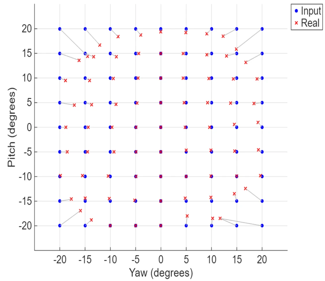
~1°Error at most positions in the angle tests
~5°Deviation near some pitch/yaw extremes
Vehicle speed is not a direct airspeed measurement. The angle results come from the separate video-based positioning check.
Commanded vs. measured angles
After changing the mount, our original encoders were no longer easy to attach. We used video to track the rocket’s deflection and compare achieved angles with the requested positions.
Most positions were within about 1°, but the error increased near the limits. Some distortion remained, and we had not fully isolated its cause. This was an improvement in much of the range, with more work needed at the extremes.
Angle test results: blue input points and red measured positions.
Vehicle attachment: extended runs loosened the roof-rack hardware. We tried a ratchet-strap arrangement afterward, but the S-hook attachment still needed refinement.
Clearance and vibration: vibration became noticeable above 65 mph, and at certain angles the actuators could contact the supporting bearings and stop moving.
Further testing: we still needed direct airspeed measurements, wind-tunnel testing, and tests with the client’s completed AFS hardware.
WHAT I LEARNED
What the prototypes taught me
Assembling the 3D-printed mount revealed problems I had missed in CAD: bearings could slide out, bolts blocked the joints, and the rocket wobbled as it rotated. Finding these problems in a printed prototype helped us improve the design before machining the parts.
I also learned to check the measuring equipment when test results looked wrong. Our sensor mount was bending and affecting the angle readings. A separate sensor showed that the rig was moving more accurately than those readings suggested.